R1200GS ‘Motolights’ Spotlights / Riding Lights
So what are Motolights? – additional spot and fog lights or riding lights from www.motolight.com There’s a choice of type/fitment but the type referred to in Marco’s article below are like these which are popular with R1200GS owners in the US. Here’s a couple of extra photos I’ve pinched from Jim Bade (aka Jim VonBaden) who produces the R1100/R1150GS and R1200Gs Maintenance DVDs


Usual disclaimer – mess with your motorcycle electrics, without knowing what you’re doing, at your peril! 🙂
R1200GS Motolight Riding Lights Installation
By Marco Hyman
Original article – visit Marco’s website: www.snafu.org
I was in my wife’s car one afternoon when I noticed a bike in the rear view mirror. I couldn’t help but notice it due to that rider’s addition of 2 amber riding lights. I decided to do something quite similar to my R1200GS. I eventually decided to go with Motolights. This was partially driven by my desire to be seen, not so much to add night-time lighting. If night-time lighting were my goal I’d probably have gone with some outboard HID lights.
Motolight has a brake caliper mounting, but I thought that would put the lights too low; at least too low for a GS. I originally thought I’d use a strap mount just above the lower fork brace. However, if the bars were right or left of center the lights would hit the plastic before the suspension bottomed, not a good thing. I mounted them just below the brace, about even with the fender.

Once the lights were physically mounted I took the tank off the bike. I wanted all wiring under the tank. I didn’t want to have to futz around with wiring just to remove the tank in the future. I also decided to re-route my power for GPS and V1 (Valentine One) radar detector while I was at it.

The lights are wired directly to the battery through a fuse, controlled by a relay. The relay is wired to a source of 12V through a switch. I picked the switched 12V that’s available at the diagnostic plug and found that I could just fit the relay and fuse under the tool tray. See the update below for a better way to get switched relay control power.

The harness from the relay goes along the right side of the bike. The harness from the two lights is cable tied to the ABS sensor wire. They come together just under the steering head, cable tied to the frame.


The switch is temporarily coiled up under the saddle. I’m not sure exactly where I’m going to put it, yet. I don’t think I’ll need the switch very often, so it can go in an out of the way place.
The last thing to do was replace the stock clear bulbs with the amber bulbs I ordered. I’ll aim the lights after I get the bike back together.
I used an accessory socket extension cable attached to the power distribution block that came with my V-1 for V-1 and GPS power. The cable is routed on the left side of the bike up to the brace that goes toward the instrument mounting from the steering head by the horn. You can just see the cable in the next picture below at the far left. The second picture is a close up of the brace with the V-1 distribution block. Before the cables were tied in place I made sure that the fork tube has clearance when in full lock. It does. Barely.


It didn’t take long to put the bike back together. That’s one of the things I like about the GS. The light switch is on, under the saddle, so the lights go on and off with the ignition switch. I made sure the lights were aimed slightly down, then took a test ride. My wife then sat in her car with the bike behind the car to get a rear-view-mirror look at things. They are noticeable. Good. They don’t blind her. Better. I’ll have to take a night ride and see how they are in the dark.


CAUTION: the placement of additional lights as above may not meet regulations/legislation requirements in some countries.
Update – alternative switched power for the lights relay:
When I wired my Motolights I took switched power for the control relay from the diagnostic plug under the back of the riders seat. This worked, but meant that the lights came on as soon as the ignition was switched on (assuming the Motolight control switch was on — almost always the case on my bike). That equates to a draw of 100 watts (about 8 amps) from the battery during the startup ritual before hitting the starter. This usually doesn’t hurt, but suppose the battery wasn’t fully charged some cold morning. That 8 amp draw could be the difference between starting the bike and looking for a jump start.
So far I’ve avoided the need for a jump start by trying to remember to turn off the aux lights before switching on the ignition on cold mornings. Not wanting to trust my (bad) memory forever, I finally decided to change the wiring to take switched power for the Motolight control relay from the headlight main beam. Since the headlight doesn’t come on until after the bike is started using it as a control signal means the Motolights won’t come on until the bike is started, too.

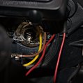
This pictures shows the plug that provided power to the headlight bucket. I pulled back the rubber rain boot to take a look. The yellow wire is what I need to tap in to for the control relay. The problem is that I can’t see how to do this without making permanent changes to the plug, cutting the plug wiring, or negating the waterproof qualities of the rubber boot. I need another way to get to that yellow wire.
I put the boot back over the connector and plugged the connector into its socket.
There are several hollow rubber L shaped tubes coming out of the headlight housing with the end of the L pointing down. I suspect they are there to vent the housing. The bottom of each breather (if that is what it is) resides just above a flat baffle molded into the plastic housing. My guess is that is to keep water from splashing up the vent. I fed some wire through the breather to the right of the main beam access port.


I pulled enough wire through the breather to give me some slack and then stripped of the end and wrapped it around the connector for the yellow wire. No crimp, no solder. This may not last, in which case I’ll try a more permanent connection method, later. For now I used a cable tie to provide stress relief. The advantage of doing it this way is that I can remove the lead and bring the bike back to 100% stock without any lasting changes to the bike.

I routed the control lead under the tank and into the space under the tool tray with the Motolight fuse and relay. A female quick disconnect was put on the control lead so it wont short the headlight should it come apart. A mail connector was added to the lead that goes to the Motolight switch.
When the switch is on any power on the control lead will be applied to the primary of the Motolight control relay, turning on the secondary which switches fused power directly from the battery to the lights.
I put the tank back on the bike, switched on the ignition, and waited for the power on test to finish. No headlamp faults. No Motolights. Good. I then started the bike. The Motolights came on with the main beam. Great! I like this much better than having to trust my memory.